If you want to open up the Nex II for modification or even just to look around, begin by removing the two screws on the back. The case is secured at the top by two clasps that lock the two halves together. By the way, most of the larger images have notes on them.
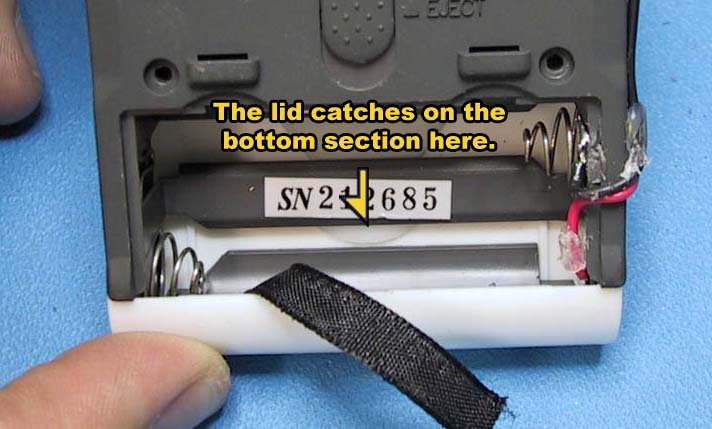 The top half will lift most of the way off and part of it will get stuck on the bottom half as shown in the picture.
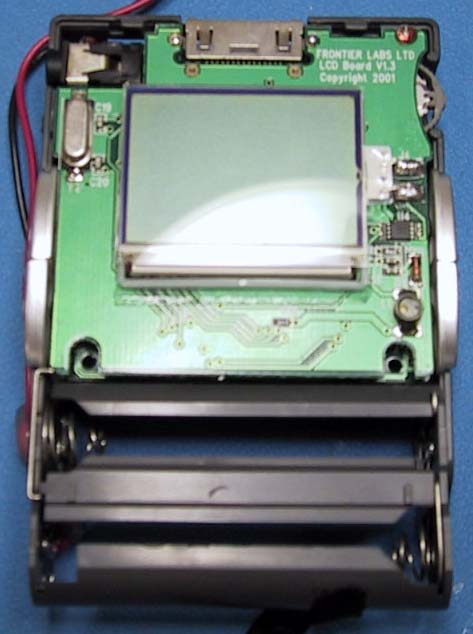
Just use a small blade screw driver or your fingernail to pull the battery holder (gray bit) towards the back to allow for removal of the top. As the top comes away, the screen may be stuck to it, either by being wedged in the square area on the upper case or by a rubber cement like glue. remove the cover plate that holds the Nexkin on and push the screen gently with your finger. Upon removal of the cover, you will see the upper PCB which holds mainly the LCD screen as well as the USB hookup.
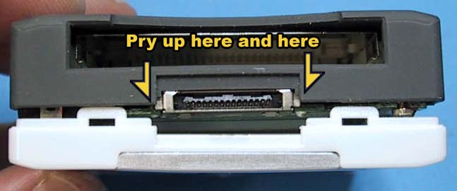
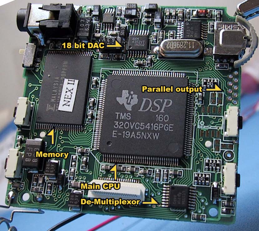 The top PCB can be removed by unscrewing the screw in the upper right corner and gently prying the lower section of the PCB away from the bottom. The bottom PCB can be removed by unscrewing the last screw in the upper left and pulling the right hand-side up first. Watch that you don't damage the lock switch which is only attached to the PCB via surface-mount soldering. Pivot the board slightly by the lower left corner to free the switch and make sure not to lose the gray external part of the switch. You may have to nudge the battery terminals from the back in order to completely remove the PCB from the case. In the full-sized photo of the bottom PCB, I've identified some of the parts. Most are fully expected, a processor of some sort, memory to work with, and a digital to analog converter. A couple bits are interesting though, the parallel output and the demultiplexor. The parallel output goes directly to parallel-out pins built into the DSP. This is most likely used by FL for debugging the firmware. The demultiplexor is pretty neat in here. As far as I can tell, the buttons each have a clock signal coming to it that is then fed into the demultiplexor together. That way, the system can easily handle having multiple buttons pressed and there are fewer traces on the PCB. (If this isn't the case, please let me know.)